Five-Axis Programming Techniques for Graphite Machining: Practical Methods to Prevent Thermal Deformation and Cutting Force Fluctuations
24 11,2025
Technical knowledge
Master the essential five-axis programming techniques tailored for graphite machining to effectively prevent thermal deformation and cutting force fluctuations. This article delves into the core logic of five-axis kinematic programming, highlighting the integration of RTCP control technology and key CAM software practices. Covering the entire workflow from coordinate system transformations to interference checks, it offers manufacturing professionals targeted strategies for graphite and similar non-metallic materials. Learn deformation prevention, toolpath optimization, and real-world case studies of complex parts such as impellers and mold cavities, designed to enhance first-pass yield and reduce trial production time.

Mastering Five-Axis CNC Programming for Graphite: Tackling Thermal Deformation and Cutting Force Fluctuations
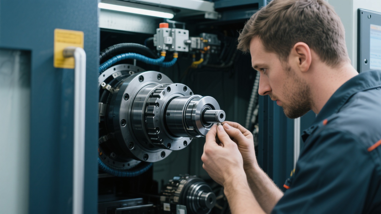
If you're working with graphite materials on five-axis CNC machines, you know the challenges well: thermal deformation and cutting force fluctuations threaten your precision and production efficiency. Understanding the core programming logic combined with advanced techniques such as RTCP (Rotating Tool Center Point) control can dramatically reduce these issues. Let’s walk through practical strategies to optimize your programming workflow, enhance part accuracy, and shorten your production cycles.
Understanding Five-Axis Programming Fundamentals and the Unique Nature of Graphite
Five-axis machining allows simultaneous movement on X, Y, Z linear axes, and two rotational axes. This capability is essential for complex geometries like impellers or mold cavities frequently made from graphite. However, graphite's brittle, porous structure and relatively low thermal conductivity create distinct challenges:
- Thermal Sensitivity: Heat accumulation can lead to micro-cracks and dimensional instability.
- Tool Wear: Graphite’s abrasiveness causes accelerated tool degradation, impacting cutting consistency.
- Chip Evacuation: Fine dust and chips can obstruct tool paths, increasing load fluctuations.
Key Causes of Thermal Deformation & How to Prevent during Programming
Thermal deformation arises primarily from frictional heat generated at the cutting zone, causing thermal expansion that shifts part geometry. In your programming phase, you can implement these controls:
| Cause |
Programming Prevention Strategy |
| High Spindle Speed & Feed Rate |
Optimize spindle speed and feed rates to avoid excessive heat buildup; use stepwise increases based on machining stage. |
| Inefficient Toolpaths |
Plan smooth, continuous toolpaths minimizing abrupt direction changes and retract motions to reduce friction peaks. |
| Poor Coolant Application |
Incorporate programmed coolant cycles or use air blow to dissipate heat at critical cutting zones. |
Employing RTCP technology can dynamically adjust tool center points compensating for machine kinematics and reducing unexpected thermal displacement. This is crucial when programming complex geometries with tight tolerances in graphite components.
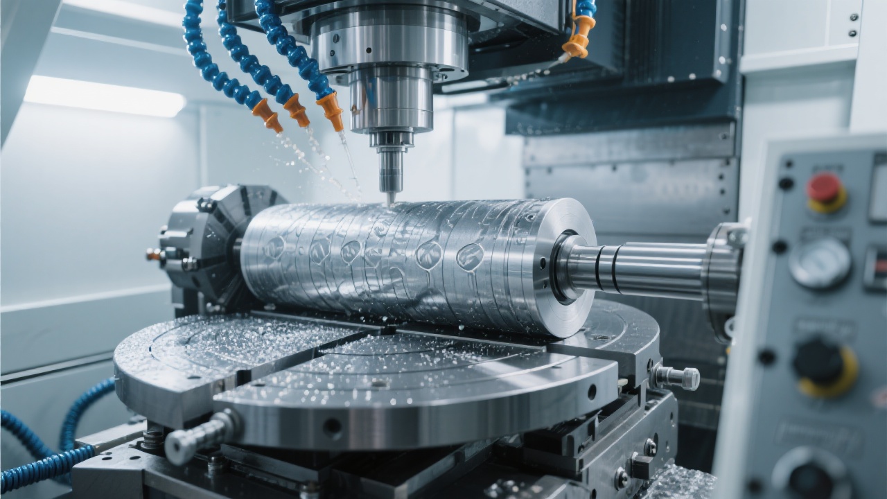
Mitigating Cutting Force Fluctuations: Precision & Surface Quality Improvement
Fluctuating cutting forces can induce vibration, accelerate tool wear, and degrade surface finish — detrimental for high-value graphite parts. To address this:
- Smooth Acceleration Profiles: Program gradual acceleration and deceleration to curb force peaks.
- Adaptive Feedrate Adjustment: Use CAM software functions that modify feed based on cutting load feedback.
- Toolpath Optimization: Avoid sharp corners and reentrant features by adjusting the tool approach angle to ensure consistent engagement.
Did you know? Implementing adaptive cutting strategies can reduce tool wear by up to 35% and improve surface finish roughness (Ra) by nearly 20% on graphite parts.
Showcasing a Typical Complex Curve Part Programming Workflow
Consider impellers with intricate blade geometries—common graphite components requiring high precision. An effective programming sequence includes:
- Coordinate System Setup & RTCP Alignment: Define machine and workpiece zero points, calibrate RTCP corrections.
- Roughing Strategy: Execute multi-pass bulk material removal with verified toolpaths to limit heat accumulation.
- Finishing Passes: Employ lower feeds and fine stepovers optimized for surface integrity.
- Interference and Collision Checks: Use CAM to simulate and verify all tool positions and avoid part/tool collisions.
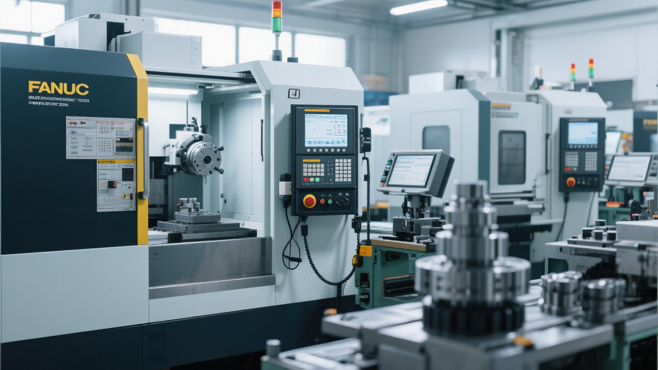
Common CAM Software Pitfalls & Standardized Process Benefits
Overlooking parameter consistency or skipping interference validation leads to scrap or costly rework. Popular CAM platforms like Mastercam and Siemens NX offer robust programming modules, but you must:
- Regularly update tool libraries with accurate graphite-specific tool data.
- Cross-check RTCP calibration after machine maintenance or tool changes.
- Maintain a documented, repeatable programming workflow to train new operators efficiently.
Establishing standardized protocols not only reduces programming errors by up to 40% but also accelerates trial runs significantly, translating into faster market-ready part delivery.